
 All news & development updates

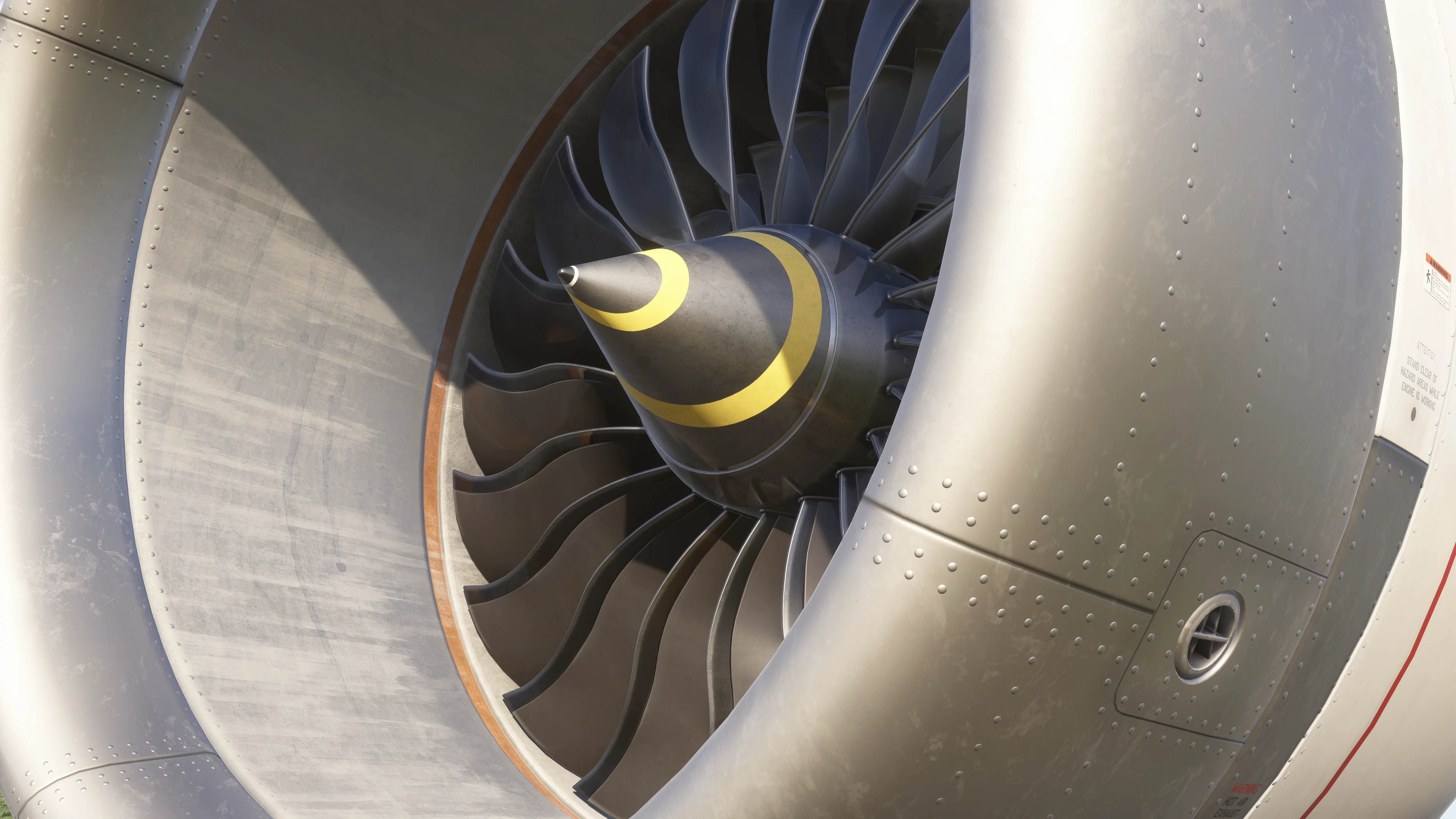
Lets talk Engines!
We’ve seen your questions and followed the discussions about our 787-9’s engines, and we’re happy to see so many of you getting into the details. We wanted to share a closer look at what we’re working on and how our team’s regular access to the real aircraft helps us along the way. The 3D model and animations are getting their final polish, but the most important part is already in place and working: the underlying systems, coded from the ground up, pipe by pipe and valve by valve. Schematic level? We meant it. And yes, we’re on track to get you flying this year.
We also went underneath the engine...
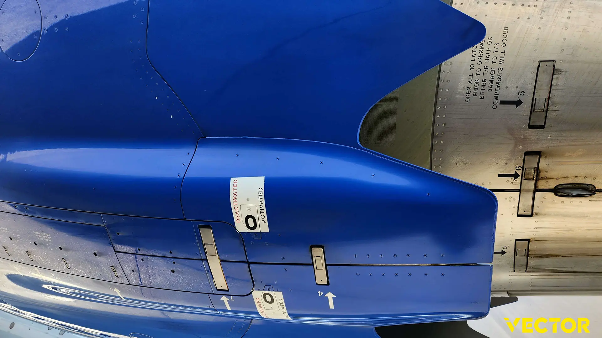
ROLLS ROYCE TRENT 1000:


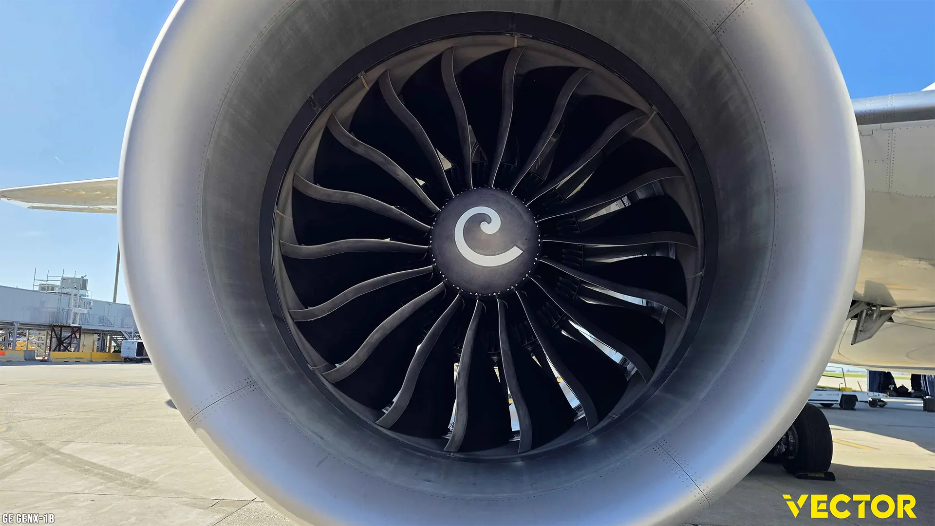
GE-GENX-1B:


The engine and fuel systems are one example of how we’ve built the VECTOR 787-9. The same depth extends across the aircraft’s other physical systems, including hydraulics, air system and electrical power, alongside the avionics and more, all modelled and coded from the ground up.
When we say schematic-level simulation, we mean it. We’ve coded the fuel system valve by valve and line by line, including electrical dependencies, pumps, sensors and control functions. That includes engine-driven pumps providing suction when the tank pumps aren’t running, fuel temperature and pressure sensing, engine fire detection and extinguishing, and much more.
These components work together during normal operation and failures large and small. A short EICAS message can be the visible result of a whole chain of events across interconnected systems (all actually happening within the simulation) . We’ve modelled that chain, so what you see in the cockpit reflects what’s physically happening underneath. Well, virtually physically.

Fuel consumption responds to engine operation and flight conditions within that same simulation. An airline dispatcher from a major carrier recently joined our team, bringing another operational perspective as we fine-tune fuel-burn profiles. After all, it’s all about fuel.
The systems, components and figures below offer a glimpse into what’s running behind our engine simulation. Each entry represents a component or function we’ve coded, with its own role and dependencies within the engine and fuel systems. These components respond to changing conditions, interact with one another and work (or don’t…), shaping everything from engine starts and thrust response to fuel consumption, failures and cockpit indications. It’s only a fraction of what’s already in place, but it helps put the scale of the work into perspective.
Vector 787-9 Engine Stats
Our Fuel System has these coded:
- 5 tanks (2 x Main, 1 x Ctr, 2 x Surge)
- 19 different fuel lines (incl. fuel Jettison)
- 9 different fuel pumps (6 x AC driven, 1 x DC driven, 2 x engine driven)
- 22 different fuel valves (11 x Fuel, 6 x Refuel, 1 x APU SOV, 2 x Scav ISO, 2 x Refuel Adapter)
- fuel temp, fuel press and fuel height sensors
- 1 x FUEL BALANCE SYSTEM
- 1 x FUEL SCAVENGE SYSTEM
- 1 x FUEL JETTISON SYSTEM
Specific Engine fuel related info:
- Suction: Engines can be running even without tank fuel pumps running as engine driven fuel pumps provide suction.
- Engine Fire and Overheat Detection implemented
- Engine Fire Extinguishing implemented
Main Engines Code
For both engines we have these items coded:
- EEC
- Main Engine Data Concentrator (data from sensors)
- MEDC
- Hydraulic Control Unit HCU
- Isolation Control Valve Assembly ICV
- Interlock Assembly Interlock Left
- Thrust Control Module TCM
- Servo Thrust Assembly
- N1 Sensor Set
- N2 Sensor Set
- N3 Sensor Set
- EGT Sensor Set
- N1 Vibration Sensor Set
- N2 Vibration Sensor Set
- P2.0 Probe Inlet Air Pressure Sensor Set
- T2.0 Inlet Temperature Sensor Set
- HP Compressor Discharge Pressure Set
- H4 Static Port Sensor Set
- H8 Static Port Sensor Set
- Starter 1 / Starter 2
- Igniter (Exciter) 1 Igniter / (Exciter) 2
- Reverser Door 1 / Reverser Door 2 / Reverser Door 3 / Reverser Door 4
- Track Lock Assembly
- Reverser Door 1/2/3/4 Proximity Sensor Set
- Track Lock Proximity Sensor Set
- Engine Oil System
- Oil Quantity Sensor Set
- Oil Pressure Sensor Set
- Oil Temperature Sensor Set
- AGB Engine Accessory Gearbox
- Overspeed Protection
- Thrust Ramping
- Thrust Control Malfunction
- Thrust Assembly Protection
- Transient Bleed System
- Idle Selection
- Minimum Idle
- Approach Idle
- Icing Idle
- Ice Crystal Anti Ice Function
- Autostart
- In-Flight Start Ignition
- Auto-Relight
- Fuel Control
- Oil Control
- Thrust Reverser
- Airborne Vibration Monitoring System
- Engine Failure Alert System
- Multiple Dual-Channel Detectors (Fire and Overheat Detection)
- Engine Fire Switches
- Engine Fire Lights
- Engine Fire Extinguisher Bottles
- Engine Fire Extinguisher Bottles Squibs
- AUTO and MANUAL mode
- OVHD switches, valves, press and temp sensors etc.
- EICAS and Maint Page display output
From the Aircraft to the Model
ROLLS ROYCE TRENT 1000:

GE-GENX-1B:

The same attention carries through to the visual model. As part of our development plan, we recently completed additional blade measurements and cross-checked references from different operators. There are differences between the Rolls-Royce and GE engines, and keeping those references specific to each engine type is an important part of the work.
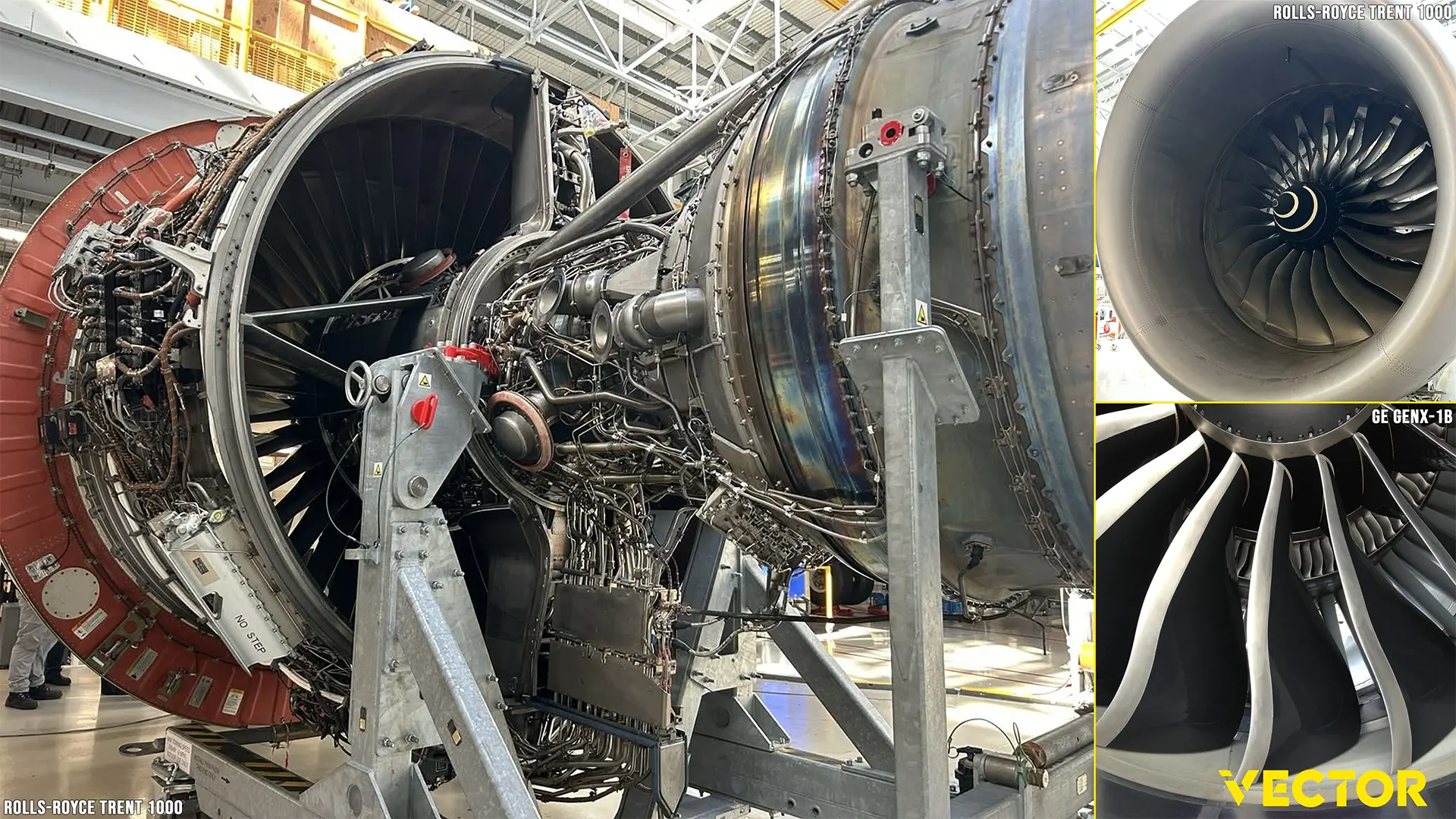

The 3D model and code are being developed together as one engine simulation, built from the ground up. Geometry, moving parts, system behavior and visual effects all need to work together, connecting what you see outside with what the aircraft is doing and what you read in the cockpit. This spotlight is a small look into that process.
ROLLS ROYCE TRENT 1000:


What’s Next
We’re preparing for a 2026 release, with external beta testing set to begin in the coming days. We’ll share a separate announcement shortly with more details. There’s plenty more to show you, and we’re looking forward to taking you deeper into the aircraft and its systems.
Thank you for your questions, feedback and enthusiasm, and for being part of the journey.
The VECTOR Team